Forked from DJMarlow/Flite_Sensor_Controller_DIY.md
Created
November 26, 2023 14:17
-
-
Save LinusU/948a44ea401e9ddee9eb6ebf58f05fc9 to your computer and use it in GitHub Desktop.
Revisions
-
DJMarlow revised this gist
Apr 22, 2022 . 1 changed file with 1 addition and 1 deletion.There are no files selected for viewing
This file contains hidden or bidirectional Unicode text that may be interpreted or compiled differently than what appears below. To review, open the file in an editor that reveals hidden Unicode characters. Learn more about bidirectional Unicode charactersOriginal file line number Diff line number Diff line change @@ -157,7 +157,7 @@ Once the second stage of epoxy has fully cured, you have finished building the F * Male 4-pin GX16 aviation connector * Wemos D1 Mini * X002BTWN2R Thingpulse Breakout Board (https://thingpulse.com/product/connector-board-for-wemos-d1-mini-pro-2-4-ili9341-tft-module/) * 2.4" SPI TFT LCD Display 2.4 Inch Touch Panel LCD ILI9341 240x320 3.3V (make sure the dimensions and header pins match the breakout board) * 22 AWG stranded wire, multiple colors recommended (Red, Black, Blue, White) ---- -
Jan 2, 2022 . 1 changed file with 1 addition and 1 deletion.There are no files selected for viewing
This file contains hidden or bidirectional Unicode text that may be interpreted or compiled differently than what appears below. To review, open the file in an editor that reveals hidden Unicode characters. Learn more about bidirectional Unicode charactersOriginal file line number Diff line number Diff line change @@ -262,7 +262,7 @@ Make sure your computer has access to the internet. Unzip and launch the application. Configure the selections as shown below (your COM port may be different and the firmware may be newer), and click "Download Firmware and Flash Controller":  -
Jan 2, 2022 . 1 changed file with 4 additions and 0 deletions.There are no files selected for viewing
This file contains hidden or bidirectional Unicode text that may be interpreted or compiled differently than what appears below. To review, open the file in an editor that reveals hidden Unicode characters. Learn more about bidirectional Unicode charactersOriginal file line number Diff line number Diff line change @@ -164,6 +164,8 @@ Once the second stage of epoxy has fully cured, you have finished building the F ### ASSEMBLY INSTRUCTIONS Note - Depending on the vendor of the Wemos D1 mini board, some may have a high rate of failure out of the box. It is recommended to comfirm that you can successfully flash the board before spending any effort to begin soldering. See flashing instructions below. Assemble the Wemos D1 Mini, breakout board, and touchscreen display using this writeup here: https://docs.thingpulse.com/guides/wifi-color-display-kit/ @@ -212,6 +214,8 @@ Snap the back cover onto the enclosure to protect the components inside. ### ASSEMBLY INSTRUCTIONS Note - Depending on the vendor of the Wemos D1 mini board, some may have a high rate of failure out of the box. It is recommended to comfirm that you can successfully flash the board before spending any effort to begin soldering. See flashing instructions below. Remove the plastic female portion of the female 4-pin GX16 connector from the connector sleeve, and solder wires to it based on pinout drawing.  -
Apr 4, 2021 . 1 changed file with 1 addition and 1 deletion.There are no files selected for viewing
This file contains hidden or bidirectional Unicode text that may be interpreted or compiled differently than what appears below. To review, open the file in an editor that reveals hidden Unicode characters. Learn more about bidirectional Unicode charactersOriginal file line number Diff line number Diff line change @@ -75,7 +75,7 @@ ---- ### BILL OF MATERIALS (Approximate cost of materials: $65) * 3D Printed Sensor Enclosure (https://www.thingiverse.com/thing:4670500) * VL53L0X TOF Breakout Board (25mm x 12.2mm board) * HSCMAND150PA4A3 Pressure and Temperature Sensor (https://www.digikey.com/en/products/detail/honeywell-sensing-and-productivity-solutions/HSCMAND150PA4A3/2416036) * Male 4-pin GX16 aviation connector -
Jan 11, 2021 . 1 changed file with 3 additions and 1 deletion.There are no files selected for viewing
This file contains hidden or bidirectional Unicode text that may be interpreted or compiled differently than what appears below. To review, open the file in an editor that reveals hidden Unicode characters. Learn more about bidirectional Unicode charactersOriginal file line number Diff line number Diff line change @@ -44,7 +44,7 @@ Because every brewer's kegerator/keezer setup is different, the Flite architecture supports different design models to accommodate this. Here is an overview of the Flite architecture, demonstrating different configuration options:  ### HOW MANY KEG SENSORS DO I NEED? You need 1 Flite keg sensor for EVERY keg you want to monitor. @@ -67,6 +67,8 @@ https://www.flitesense.com/taplistio-support * BruControl - A Windows-based software for developing custom HMI (Human Machine Interface) graphics for your brewery sensors and leveraging scripting to automate control. * KegScreen - A free open-source web server that reads the local Flite controllers and displays the data on a monitor connected to a Raspberry Pi. This project is in progress, more details to come soon! **Building a Flite Keg Lid Sensor** -
Dec 10, 2020 . 1 changed file with 3 additions and 3 deletions.There are no files selected for viewing
This file contains hidden or bidirectional Unicode text that may be interpreted or compiled differently than what appears below. To review, open the file in an editor that reveals hidden Unicode characters. Learn more about bidirectional Unicode charactersOriginal file line number Diff line number Diff line change @@ -79,7 +79,7 @@ * Male 4-pin GX16 aviation connector * Corny keg lid * Food grade epoxy (recommend ZDSticky) * 22 AWG stranded wire, multiple colors recommended (Red, Black, Blue, White) ---- @@ -156,7 +156,7 @@ Once the second stage of epoxy has fully cured, you have finished building the F * Wemos D1 Mini * X002BTWN2R Thingpulse Breakout Board (https://thingpulse.com/product/connector-board-for-wemos-d1-mini-pro-2-4-ili9341-tft-module/) * 2.4" SPI TFT LCD Display 2.4 Inch Touch Panel LCD ILI9341 240x320 3.3V * 22 AWG stranded wire, multiple colors recommended (Red, Black, Blue, White) ---- @@ -204,7 +204,7 @@ Snap the back cover onto the enclosure to protect the components inside. * 3D Printed Headless Enclosure (https://www.thingiverse.com/thing:4670505) * Female 4-pin GX16 aviation connector * Wemos D1 Mini * 22 AWG stranded wire, multiple colors recommended (Red, Black, Blue, White) ---- -
Dec 10, 2020 . 1 changed file with 1 addition and 1 deletion.There are no files selected for viewing
This file contains hidden or bidirectional Unicode text that may be interpreted or compiled differently than what appears below. To review, open the file in an editor that reveals hidden Unicode characters. Learn more about bidirectional Unicode charactersOriginal file line number Diff line number Diff line change @@ -79,7 +79,7 @@ * Male 4-pin GX16 aviation connector * Corny keg lid * Food grade epoxy (recommend ZDSticky) * 22 AWG wire, multiple colors recommended (Red, Black, Blue, White) ---- -
Dec 10, 2020 . 1 changed file with 1 addition and 1 deletion.There are no files selected for viewing
This file contains hidden or bidirectional Unicode text that may be interpreted or compiled differently than what appears below. To review, open the file in an editor that reveals hidden Unicode characters. Learn more about bidirectional Unicode charactersOriginal file line number Diff line number Diff line change @@ -78,7 +78,7 @@ * HSCMAND150PA4A3 Pressure and Temperature Sensor (https://www.digikey.com/en/products/detail/honeywell-sensing-and-productivity-solutions/HSCMAND150PA4A3/2416036) * Male 4-pin GX16 aviation connector * Corny keg lid * Food grade epoxy (recommend ZDSticky) * QTY:4 Approximately 4" 22 AWG wires (Red, Black, Blue, White) ---- -
Dec 10, 2020 . 1 changed file with 1 addition and 1 deletion.There are no files selected for viewing
This file contains hidden or bidirectional Unicode text that may be interpreted or compiled differently than what appears below. To review, open the file in an editor that reveals hidden Unicode characters. Learn more about bidirectional Unicode charactersOriginal file line number Diff line number Diff line change @@ -8,7 +8,7 @@ * Drill press with drill bits for stainless steel * Soldering iron * 3D printer * Computer with BrewFlasher(https://www.brewflasher.com/) **SKILLS** -
Dec 4, 2020 . 1 changed file with 1 addition and 1 deletion.There are no files selected for viewing
This file contains hidden or bidirectional Unicode text that may be interpreted or compiled differently than what appears below. To review, open the file in an editor that reveals hidden Unicode characters. Learn more about bidirectional Unicode charactersOriginal file line number Diff line number Diff line change @@ -42,7 +42,7 @@ **Design Considerations** ---- Because every brewer's kegerator/keezer setup is different, the Flite architecture supports different design models to accommodate this. Here is an overview of the Flite architecture, demonstrating different configuration options: 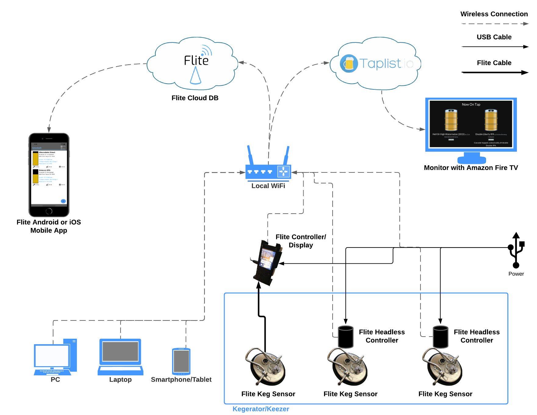 -
Dec 4, 2020 . 1 changed file with 7 additions and 1 deletion.There are no files selected for viewing
This file contains hidden or bidirectional Unicode text that may be interpreted or compiled differently than what appears below. To review, open the file in an editor that reveals hidden Unicode characters. Learn more about bidirectional Unicode charactersOriginal file line number Diff line number Diff line change @@ -250,7 +250,13 @@ Download the BrewFlasher desktop application for Windows or MacOS here: https://github.com/thorrak/brewflasher/releases Plug the Flite controller into your computer via micro USB cable. Make sure your computer has access to the internet. Unzip and launch the application. Configure the selections as shown below, and click "Download Firmware and Flash Controller":  -
Dec 4, 2020 . 1 changed file with 11 additions and 3 deletions.There are no files selected for viewing
This file contains hidden or bidirectional Unicode text that may be interpreted or compiled differently than what appears below. To review, open the file in an editor that reveals hidden Unicode characters. Learn more about bidirectional Unicode charactersOriginal file line number Diff line number Diff line change @@ -242,11 +242,19 @@ Snap the lid onto the enclosure, and plug the Flite headless controller into the **Programming a Flite Display or Headless Controller** ---- Flite is supported by BrewFlasher, which is a free software for flashing the Flite firmware to your controller.  Download the BrewFlasher desktop application for Windows or MacOS here: https://github.com/thorrak/brewflasher/releases Unzip and launch the application. Configure the selections as shown below:  Cycle power to your Flite controller. You have succesfully built and programmed your Flite controller! Follow instructions to calibrate and configure Flite in the User's Guide here: -
Dec 2, 2020 . 1 changed file with 3 additions and 3 deletions.There are no files selected for viewing
This file contains hidden or bidirectional Unicode text that may be interpreted or compiled differently than what appears below. To review, open the file in an editor that reveals hidden Unicode characters. Learn more about bidirectional Unicode charactersOriginal file line number Diff line number Diff line change @@ -107,7 +107,7 @@ Solder wires to 4-pin GX16 connector based on pinout drawing.   Place a small bead of loctite, or some type of fast-acting glue around both sensor openings on the sensor enclosure, and install the sensors in their respective openings. @@ -170,7 +170,7 @@ Solder wires to 4-pin GX16 connector based on pinout drawing.   (**RECOMMENDED**) Using loctite or some type of fast-drying glue, place a bead around the 4-pin GX16 connector in the inside of the enclosure's bottom cavity, make sure this is sealed. Pour food grade epoxy into bottom cavity of enclosure. This is an optional step, but I have found that epoxy keeps the connector from rotating and provides a solid base for mounting. @@ -214,7 +214,7 @@ Remove the plastic female portion of the female 4-pin GX16 connector from the co   Firmly press female connector into the bottom of the Flite headless enclosure. This should be a tight fit! -
Dec 2, 2020 . 1 changed file with 3 additions and 0 deletions.There are no files selected for viewing
This file contains hidden or bidirectional Unicode text that may be interpreted or compiled differently than what appears below. To review, open the file in an editor that reveals hidden Unicode characters. Learn more about bidirectional Unicode charactersOriginal file line number Diff line number Diff line change @@ -79,6 +79,7 @@ * Male 4-pin GX16 aviation connector * Corny keg lid * Food grade epoxy * QTY:4 Approximately 4" 22 AWG wires (Red, Black, Blue, White) ---- @@ -155,6 +156,7 @@ Once the second stage of epoxy has fully cured, you have finished building the F * Wemos D1 Mini * X002BTWN2R Thingpulse Breakout Board (https://thingpulse.com/product/connector-board-for-wemos-d1-mini-pro-2-4-ili9341-tft-module/) * 2.4" SPI TFT LCD Display 2.4 Inch Touch Panel LCD ILI9341 240x320 3.3V * QTY:4 Approximately 4" 22 AWG wires (Red, Black, Blue, White) ---- @@ -202,6 +204,7 @@ Snap the back cover onto the enclosure to protect the components inside. * 3D Printed Headless Enclosure (https://www.thingiverse.com/thing:4670505) * Female 4-pin GX16 aviation connector * Wemos D1 Mini * QTY:4 Approximately 4" 22 AWG wires (Red, Black, Blue, White) ---- -
Dec 2, 2020 . 1 changed file with 6 additions and 6 deletions.There are no files selected for viewing
This file contains hidden or bidirectional Unicode text that may be interpreted or compiled differently than what appears below. To review, open the file in an editor that reveals hidden Unicode characters. Learn more about bidirectional Unicode charactersOriginal file line number Diff line number Diff line change @@ -8,7 +8,7 @@ * Drill press with drill bits for stainless steel * Soldering iron * 3D printer * Computer with PlatformIO (https://platformio.org/install/ide?install=vscode) **SKILLS** @@ -72,10 +72,10 @@ **Building a Flite Keg Lid Sensor** ---- ### BILL OF MATERIALS (Approximate cost of materials: $65) * 3D Printed Sensor Enclosure (https://www.thingiverse.com/thing:4670817) * VL53L0X TOF Breakout Board (25mm x 12.2mm board) * HSCMAND150PA4A3 Pressure and Temperature Sensor (https://www.digikey.com/en/products/detail/honeywell-sensing-and-productivity-solutions/HSCMAND150PA4A3/2416036) * Male 4-pin GX16 aviation connector * Corny keg lid * Food grade epoxy @@ -84,7 +84,7 @@ ### ASSEMBLY INSTRUCTIONS Drill a 5/8" hole in the corny keg lid using a stepper bit for stainless steel. This hold should be centered between the lid handle mounting brackets, and approximately halfway between the PRV and the lip of the lid.  @@ -148,7 +148,7 @@ Once the second stage of epoxy has fully cured, you have finished building the F **Building a Flite Display Controller** ---- ### BILL OF MATERIALS (Approximate cost of materials: $35) * 3D Printed Display Enclosure (https://www.thingiverse.com/thing:4670782) * QTY:4 M3-0.5 x 15mm Socket Cap Screws (Black) * Male 4-pin GX16 aviation connector @@ -198,7 +198,7 @@ Snap the back cover onto the enclosure to protect the components inside. **Building a Flite Headless Controller** ---- ### BILL OF MATERIALS (Approximate cost of materials: $15) * 3D Printed Headless Enclosure (https://www.thingiverse.com/thing:4670505) * Female 4-pin GX16 aviation connector * Wemos D1 Mini -
Dec 2, 2020 . 1 changed file with 1 addition and 1 deletion.There are no files selected for viewing
This file contains hidden or bidirectional Unicode text that may be interpreted or compiled differently than what appears below. To review, open the file in an editor that reveals hidden Unicode characters. Learn more about bidirectional Unicode charactersOriginal file line number Diff line number Diff line change @@ -170,7 +170,7 @@ Solder wires to 4-pin GX16 connector based on pinout drawing.  (**RECOMMENDED**) Using loctite or some type of fast-drying glue, place a bead around the 4-pin GX16 connector in the inside of the enclosure's bottom cavity, make sure this is sealed. Pour food grade epoxy into bottom cavity of enclosure. This is an optional step, but I have found that epoxy keeps the connector from rotating and provides a solid base for mounting.  -
Dec 1, 2020 . 1 changed file with 0 additions and 12 deletions.There are no files selected for viewing
This file contains hidden or bidirectional Unicode text that may be interpreted or compiled differently than what appears below. To review, open the file in an editor that reveals hidden Unicode characters. Learn more about bidirectional Unicode charactersOriginal file line number Diff line number Diff line change @@ -39,18 +39,6 @@ The Flite headless controller has all of the same capabilities as the Flite controller with display, minus the touchscreen display. The Flite headless controller is designed to install directly on the Flite keg lid sensor, eliminating the need to mount an external display and route the female-to-female 4-pin GX16 aviation socket cable. This does still require a micro USB cable for power. **Design Considerations** ---- -
Dec 1, 2020 . 1 changed file with 2 additions and 1 deletion.There are no files selected for viewing
This file contains hidden or bidirectional Unicode text that may be interpreted or compiled differently than what appears below. To review, open the file in an editor that reveals hidden Unicode characters. Learn more about bidirectional Unicode charactersOriginal file line number Diff line number Diff line change @@ -96,8 +96,9 @@ ### ASSEMBLY INSTRUCTIONS Drill a 5/8" hole in the corny keg lid. This hold should be centered between the lid handle mounting brackets, and approximately halfway between the PRV and the lip of the lid.  Install male 4-pin GX16 connector to keg lid with sensor enclosure cover. -
Dec 1, 2020 . 1 changed file with 1 addition and 3 deletions.There are no files selected for viewing
This file contains hidden or bidirectional Unicode text that may be interpreted or compiled differently than what appears below. To review, open the file in an editor that reveals hidden Unicode characters. Learn more about bidirectional Unicode charactersOriginal file line number Diff line number Diff line change @@ -79,9 +79,7 @@ https://www.flitesense.com/taplistio-support * KegScreen - A free open-source web server that reads the local Flite controllers and displays the data on a monitor connected to a Raspberry Pi. This project is in progress, more details to come soon! **Building a Flite Keg Lid Sensor** ---- -
Nov 30, 2020 . 1 changed file with 1 addition and 1 deletion.There are no files selected for viewing
This file contains hidden or bidirectional Unicode text that may be interpreted or compiled differently than what appears below. To review, open the file in an editor that reveals hidden Unicode characters. Learn more about bidirectional Unicode charactersOriginal file line number Diff line number Diff line change @@ -35,7 +35,7 @@ * Update to taplist.io API (https://www.flitesense.com/taplistio-support) ### FLITE HEADLESS CONTROLLER  The Flite headless controller has all of the same capabilities as the Flite controller with display, minus the touchscreen display. The Flite headless controller is designed to install directly on the Flite keg lid sensor, eliminating the need to mount an external display and route the female-to-female 4-pin GX16 aviation socket cable. This does still require a micro USB cable for power. -
Nov 30, 2020 . 1 changed file with 1 addition and 1 deletion.There are no files selected for viewing
This file contains hidden or bidirectional Unicode text that may be interpreted or compiled differently than what appears below. To review, open the file in an editor that reveals hidden Unicode characters. Learn more about bidirectional Unicode charactersOriginal file line number Diff line number Diff line change @@ -87,7 +87,7 @@ ---- ### BILL OF MATERIALS * 3D Printed Sensor Enclosure (https://www.thingiverse.com/thing:4670817) * VL53L0X TOF Breakout Board (25mm x 12.2mm board) * HSCMAND150PA4A3 Pressure and Temperature Sensor * Male 4-pin GX16 aviation connector -
Nov 30, 2020 . 1 changed file with 13 additions and 1 deletion.There are no files selected for viewing
This file contains hidden or bidirectional Unicode text that may be interpreted or compiled differently than what appears below. To review, open the file in an editor that reveals hidden Unicode characters. Learn more about bidirectional Unicode charactersOriginal file line number Diff line number Diff line change @@ -38,7 +38,19 @@ 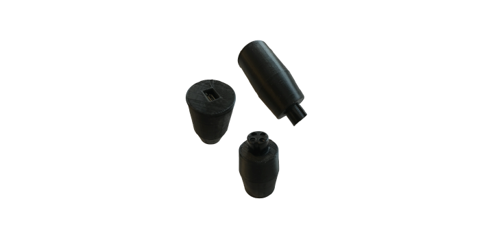 The Flite headless controller has all of the same capabilities as the Flite controller with display, minus the touchscreen display. The Flite headless controller is designed to install directly on the Flite keg lid sensor, eliminating the need to mount an external display and route the female-to-female 4-pin GX16 aviation socket cable. This does still require a micro USB cable for power. **Quick Links** ---- * [Design Considerations](https://gist.github.com/DJMarlow/6e379bbdc4a7a989cb9a6dd93ef59eaf#design-considerations) * [Building a Flite Keg Lid Sensor](https://gist.github.com/DJMarlow/6e379bbdc4a7a989cb9a6dd93ef59eaf#building-a-flite-keg-lid-sensor) * [Building a Flite Display Controller](https://gist.github.com/DJMarlow/6e379bbdc4a7a989cb9a6dd93ef59eaf#building-a-flite-display-controller) * [Building a Flite Headless Controller](https://gist.github.com/DJMarlow/6e379bbdc4a7a989cb9a6dd93ef59eaf#building-a-flite-headless-controller) * [Programming a Flite Display or Headless Controller](https://gist.github.com/DJMarlow/6e379bbdc4a7a989cb9a6dd93ef59eaf#programming-a-flite-display-or-headless-controller) **Design Considerations** ---- -
Nov 30, 2020 . 1 changed file with 1 addition and 1 deletion.There are no files selected for viewing
This file contains hidden or bidirectional Unicode text that may be interpreted or compiled differently than what appears below. To review, open the file in an editor that reveals hidden Unicode characters. Learn more about bidirectional Unicode charactersOriginal file line number Diff line number Diff line change @@ -150,7 +150,7 @@ Once the second stage of epoxy has fully cured, you have finished building the F ---- ### BILL OF MATERIALS * 3D Printed Display Enclosure (https://www.thingiverse.com/thing:4670782) * QTY:4 M3-0.5 x 15mm Socket Cap Screws (Black) * Male 4-pin GX16 aviation connector * Wemos D1 Mini -
Nov 30, 2020 . 1 changed file with 7 additions and 1 deletion.There are no files selected for viewing
This file contains hidden or bidirectional Unicode text that may be interpreted or compiled differently than what appears below. To review, open the file in an editor that reveals hidden Unicode characters. Learn more about bidirectional Unicode charactersOriginal file line number Diff line number Diff line change @@ -53,16 +53,22 @@ You need 1 Flite display OR Flite headless controller per Flite keg sensor. ### SHOULD I USE A FLITE DISPLAY OR HEADLESS CONTROLLER? This ultimately depends on the number of kegs you have, how you would like to view your data, and how you would like to configure/calibrate your sensor when needed. If you have only a couple of kegs, the Flite display is likely the best option, as it has a local display that can be mounted near your taps. If you have more than a couple of kegs or plan to build out to more than a couple of kegs, you may want a monitor to display your data. If this is the case, a Flite display IS NOT required to connect the sensor to the monitor, and a headless option is simpler and cheaper to install. Be aware that calibrating the Flite headless controller requires you to browse the local web server, so you should be comfortable with that. More information on calibration using the web server can be found in the Flite User's Guide here: https://www.flitesense.com/support ### OK... A MONITOR DISPLAYING MY KEG DATA SOUNDS COOL, WHAT OPTIONS ARE SUPPORTED? Currently there are two options supported for a monitor displaying your keg data: * Taplist.io - A cloud-based subscription service. The Flite controller can be configured to automatically update your kegs, and you can view and display your "keg room" on any monitor with internet access. More integration support can be found here: https://www.flitesense.com/taplistio-support * KegScreen - A free open-source web server that reads the local Flite controllers and displays the data on a monitor connected to a Raspberry Pi. More integration support can be found here: TODO **Building a Flite Keg Lid Sensor** -
Nov 30, 2020 . 1 changed file with 1 addition and 1 deletion.There are no files selected for viewing
This file contains hidden or bidirectional Unicode text that may be interpreted or compiled differently than what appears below. To review, open the file in an editor that reveals hidden Unicode characters. Learn more about bidirectional Unicode charactersOriginal file line number Diff line number Diff line change @@ -69,7 +69,7 @@ ---- ### BILL OF MATERIALS * 3D Printed Sensor Enclosure (https://www.thingiverse.com/thing:4670722) * VL53L0X TOF Breakout Board (25mm x 12.2mm board) * HSCMAND150PA4A3 Pressure and Temperature Sensor * Male 4-pin GX16 aviation connector -
Nov 30, 2020 . 1 changed file with 1 addition and 1 deletion.There are no files selected for viewing
This file contains hidden or bidirectional Unicode text that may be interpreted or compiled differently than what appears below. To review, open the file in an editor that reveals hidden Unicode characters. Learn more about bidirectional Unicode charactersOriginal file line number Diff line number Diff line change @@ -144,7 +144,7 @@ Once the second stage of epoxy has fully cured, you have finished building the F ---- ### BILL OF MATERIALS * 3D Printed Display Enclosure (TODO - Add thingiverse link) * QTY:4 M3-0.5 x 15mm Socket Cap Screws (Black) * Male 4-pin GX16 aviation connector * Wemos D1 Mini -
Nov 30, 2020 . 1 changed file with 1 addition and 1 deletion.There are no files selected for viewing
This file contains hidden or bidirectional Unicode text that may be interpreted or compiled differently than what appears below. To review, open the file in an editor that reveals hidden Unicode characters. Learn more about bidirectional Unicode charactersOriginal file line number Diff line number Diff line change @@ -35,7 +35,7 @@ * Update to taplist.io API (https://www.flitesense.com/taplistio-support) ### FLITE HEADLESS CONTROLLER  The Flite headless controller has all of the same capabilities as the Flite controller with display, minus the touchscreen display. The Flite headless controller is designed to install directly on the Flite keg lid sensor, eliminating the need to mount an external display and route the female-to-female 4-pin GX16 aviation socket cable. This does still require a micro USB cable for power. -
Nov 30, 2020 . 1 changed file with 1 addition and 1 deletion.There are no files selected for viewing
This file contains hidden or bidirectional Unicode text that may be interpreted or compiled differently than what appears below. To review, open the file in an editor that reveals hidden Unicode characters. Learn more about bidirectional Unicode charactersOriginal file line number Diff line number Diff line change @@ -212,7 +212,7 @@ Firmly press female connector into the bottom of the Flite headless enclosure.  Pour a small amount of fast-acting glue into the bottom of the headless enclosure where the female connector is installed. You can also add epoxy here if desired, just make sure not to fill past the shelf. The Wemos D1 Mini will rest on this shelf.  -
Nov 30, 2020 . 1 changed file with 45 additions and 1 deletion.There are no files selected for viewing
This file contains hidden or bidirectional Unicode text that may be interpreted or compiled differently than what appears below. To review, open the file in an editor that reveals hidden Unicode characters. Learn more about bidirectional Unicode charactersOriginal file line number Diff line number Diff line change @@ -84,18 +84,21 @@ TODO - Add picture with drill press Install male 4-pin GX16 connector to keg lid with sensor enclosure cover.   Solder wires to VL53L0X sensor and HSC pressure/temperature sensor based on pinout drawings.    Solder wires to 4-pin GX16 connector based on pinout drawing.  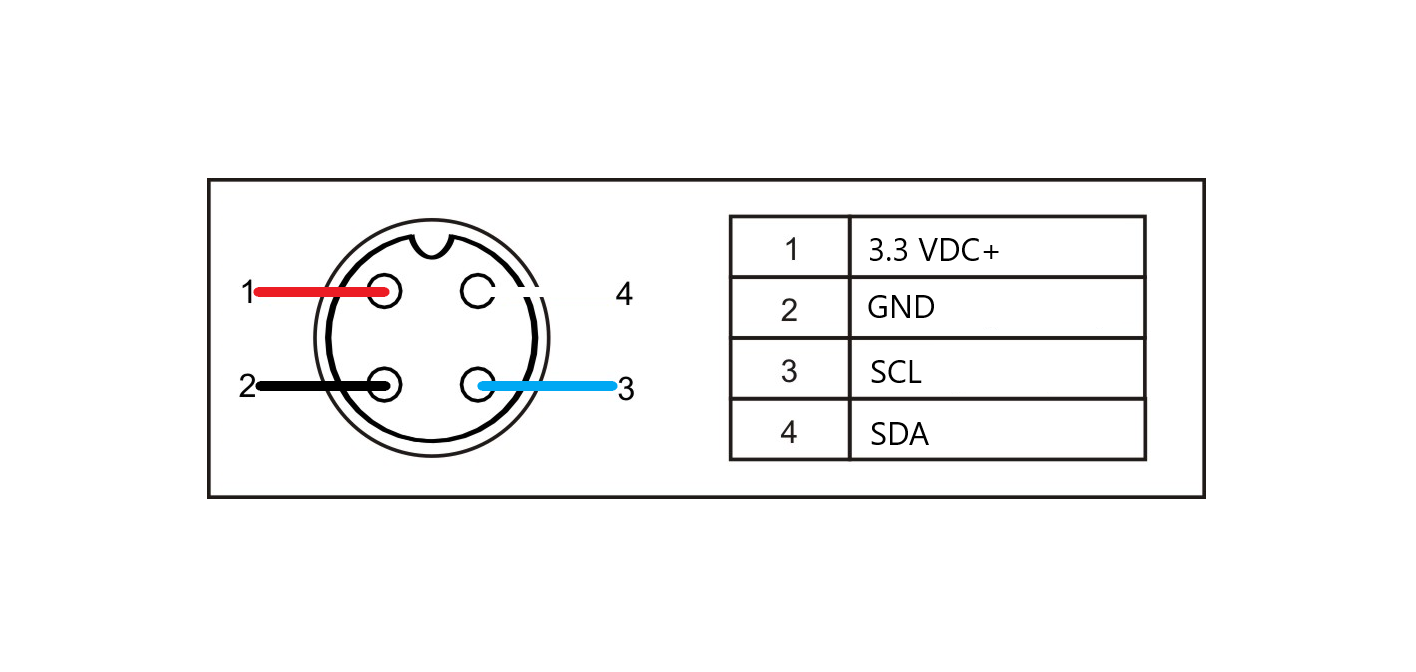 @@ -106,28 +109,35 @@ Place a small bead of loctite, or some type of fast-acting glue around both sens This is the most critical part of this assembly. There must be a seal between the sensors and the openings. You will pour epoxy into this enclosure in the next step, and if it's not sealed, it will leak out and make a mess (ask me how I know). Take your time and make sure this is sealed well, and make sure there is not any glue residue over the VL53L0X sensor face or the pressure sensor nipple.   Coil wires into sensor enclosure, do a quick test fit to make sure you can close up the enclosure.  Pour epoxy until the level is high enough for the "legs" of the enclosure lid to make contact with the epoxy. Holding the enclosure level, install the lid onto the enclosure, and wipe any residual epoxy around the enclosure.  Place lids SENSOR SIDE DOWN on the edge of a surface allowing the pressure nipple to extrude over the edge. You may want to add weight above the connector to keep the lid from tipping over. I have found sockets are quite useful for this.   After the first stage of epoxy has fully cured, apply a bead of loctite or fast-acting glue along the edge of the sensor enclosure where the sensor meets the underside of the corny keg lid.  Using something to keep the lid level (see the foam insert in picture below), pour epoxy into the underside of the corny keg lid. Pour until the sensor enclosure and lid mating surface is covered, but don't pour past the PRV.  Once the second stage of epoxy has fully cured, you have finished building the Flite keg lid sensor!  **Building a Flite Display Controller** @@ -146,31 +156,38 @@ Once the second stage of epoxy has fully cured, you have finished building the F ### ASSEMBLY INSTRUCTIONS Assemble the Wemos D1 Mini, breakout board, and touchscreen display using this writeup here: https://docs.thingpulse.com/guides/wifi-color-display-kit/ Solder wires to 4-pin GX16 connector based on pinout drawing.   (Optional) Using loctite or some type of fast-drying glue, place a bead around the 4-pin GX16 connector in the inside of the enclosure's bottom cavity, make sure this is sealed. Pour food grade epoxy into bottom cavity of enclosure. This is an optional step, but I have found that epoxy keeps the connector from rotating and provides a solid base for mounting.  Thread the socket cap screws through the screw holes and through the display and breakout board. These will cut the threads into the enclosure as you screw them in. The board should be secured and flush with the enclosure face when finished.   Solder the wires from the connector to the header pins on the Wemos D1 Mini. ``` Red - 3V3 Black - G Blue - Rx White - Tx ```  Snap the back cover onto the enclosure to protect the components inside.  **Building a Flite Headless Controller** @@ -185,7 +202,34 @@ Snap the back cover onto the enclosure to protect the components inside. ### ASSEMBLY INSTRUCTIONS Remove the plastic female portion of the female 4-pin GX16 connector from the connector sleeve, and solder wires to it based on pinout drawing.   Firmly press female connector into the bottom of the Flite headless enclosure. This should be a tight fit!  Pour a small amount of fast-acting glue into the bottom of the headless enclosure where the female connector is isntalled. You can also add epoxy here if desired, just make sure not to fill past the shelf. The Wemos D1 Mini will rest on this shelf.  Solder the wires from the connector to the Wemos D1 Mini board. ``` Red - 3V3 Black - G Blue - Rx White - Tx ``` Install the board in the enclosure channel USB side up. You may need to use a small screwdriver to help move wires out of the way so the Wemos D1 Mini board sits flush on the shelf, and is flush with the top of the enclosure. Snap the lid onto the enclosure, and plug the Flite headless controller into the Flite keg sensor lid.  **Programming a Flite Display or Headless Controller** ---- -
Nov 30, 2020 . 1 changed file with 5 additions and 0 deletions.There are no files selected for viewing
This file contains hidden or bidirectional Unicode text that may be interpreted or compiled differently than what appears below. To review, open the file in an editor that reveals hidden Unicode characters. Learn more about bidirectional Unicode charactersOriginal file line number Diff line number Diff line change @@ -191,6 +191,11 @@ Assemble the Wemos D1 Mini, breakout board, and touchscreen display using this w ---- Using PlatformIO, clone the following git repository: https://github.com/DJMarlow/FliteController Upload to your Flite controller via USB micro cable. Follow instructions to calibrate and configure Flite in the User's Guide here: https://www.flitesense.com/support
NewerOlder