-
-
Save X3msnake/63bcf7a61b68baf8cc1d3170f0b7aa15 to your computer and use it in GitHub Desktop.
| #Mesuring Resonance with ADXL345 | |
| # https://www.klipper3d.org/Measuring_Resonances.html | |
| #SSH | |
| # Install numpy (20min+) | |
| # ~/klippy-env/bin/pip install -v numpy | |
| #Install additional dependencies | |
| # sudo apt update | |
| # sudo apt install python-numpy python-matplotlib | |
| #Enable RPI as additional MCU (if not already enabled) | |
| # Install the rc script | |
| # cd ~/klipper/ | |
| # sudo cp "./scripts/klipper-mcu-start.sh" /etc/init.d/klipper_mcu | |
| # sudo update-rc.d klipper_mcu defaults | |
| # Enable SPI in piconfig | |
| # sudo raspi-config | |
| # Interfacing options -> SPI -> YES -> OK -> Finish | |
| # Build secondary microcontroller code | |
| # cd ~/klipper/ | |
| # make menuconfig | |
| # Microcontroller Architecture -> Linux process -> exit -> save | |
| # Install secondary mcu code | |
| # sudo service klipper stop | |
| # make flash | |
| # sudo service klipper start | |
| # Changes to printer config | |
| [mcu rpi] | |
| serial: /tmp/klipper_host_mcu | |
| [adxl345] | |
| cs_pin: rpi:None | |
| [resonance_tester] | |
| accel_chip: adxl345 | |
| probe_points: | |
| 148,105,20 # Probe point is the nozzle position when testing; Ideally center bed slightly above it | |
| # If all goes well one can test and use the sensor via the fluidd console with these commands | |
| # To query and confirm installation on fluidd command terminal | |
| # ACCELEROMETER_QUERY | |
| # To check the sensor noise; OK = between 1-100 ; Above 1K = sensor problems | |
| # MEASURE_AXES_NOISE | |
| # To do the test | |
| # TEST_RESONANCES AXIS=X | |
| # TEST_RESONANCES AXIS=Y | |
| # TEST_RESONANCES will generate 2 CSV files (/tmp/resonances_x_*.csv and /tmp/resonances_y_*.csv). These files can be processed with the stand-alone script on a Raspberry Pi. To do that, run running the following commands: | |
| # ~/klipper/scripts/calibrate_shaper.py /tmp/resonances_x_*.csv -o /tmp/shaper_calibrate_x.png | |
| # ~/klipper/scripts/calibrate_shaper.py /tmp/resonances_y_*.csv -o /tmp/shaper_calibrate_y.png |
| # Custom Printer Config | |
| [include witbox2_printer.cfg] | |
| # Custom Macros | |
| [include witbox2_macros.cfg] | |
| # Custom Menus | |
| [include witbox2_menus.cfg] | |
| # Input Shaper Sensor | |
| [include adxl345_sensor.cfg] | |
| # Heatbed external board atmega 328p | |
| [include witbox2_heatbed_mcu.cfg] | |
| #*# <---------------------- SAVE_CONFIG ----------------------> | |
| #*# DO NOT EDIT THIS BLOCK OR BELOW. The contents are auto-generated. | |
| #*# | |
| #*# [extruder] | |
| #*# control = pid | |
| #*# pid_kp = 28.612 | |
| #*# pid_ki = 1.490 | |
| #*# pid_kd = 137.337 | |
| #*# | |
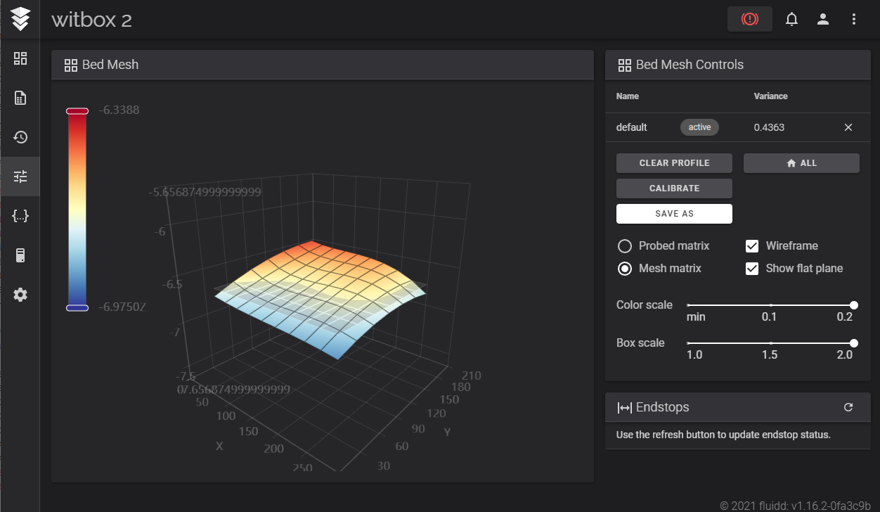
| #*# [bed_mesh default] | |
| #*# version = 1 | |
| #*# points = | |
| #*# -0.331250, -0.481250, -0.600000, -0.695000, -0.855000 | |
| #*# -0.223750, -0.395000, -0.520000, -0.632500, -0.785000 | |
| #*# -0.138750, -0.325000, -0.437500, -0.571250, -0.773750 | |
| #*# -0.143750, -0.302500, -0.405000, -0.568750, -0.867500 | |
| #*# tension = 0.2 | |
| #*# min_x = 30.0 | |
| #*# algo = lagrange | |
| #*# y_count = 4 | |
| #*# mesh_y_pps = 2 | |
| #*# min_y = 27.0 | |
| #*# x_count = 5 | |
| #*# max_y = 183.0 | |
| #*# mesh_x_pps = 2 | |
| #*# max_x = 267.0 |
| # The "heatbed_mcu" micro-controller will be used to control the heaters. | |
| [thermistor Trianglelab-NTC100K-B3950] | |
| temperature1: 25 | |
| resistance1: 103180 | |
| temperature2: 150 | |
| resistance2: 1366.2 | |
| temperature3: 250 | |
| resistance3: 168.6 | |
| [mcu heatbed_mcu] | |
| serial: /dev/serial/by-id/usb-1a86_USB_Serial-if00-port0 | |
| [heater_bed] | |
| heater_pin: heatbed_mcu:PD2 | |
| sensor_type: Trianglelab-NTC100K-B3950 | |
| pullup_resistor: 4700 | |
| sensor_pin: heatbed_mcu:PC5 | |
| control: watermark | |
| min_temp: 0 | |
| max_temp: 130 | |
| # https://3dprinterchat.com/heated-bed-too-slow-to-heat-check-some-possible-fixes/ | |
| # https://github.com/Klipper3d/klipper/blob/master/docs/Config_Reference.md#verify_heater | |
| [verify_heater heater_bed] | |
| #max_error: 120 | |
| # The maximum "cumulative temperature error" before raising an | |
| # error. Smaller values result in stricter checking and larger | |
| # values allow for more time before an error is reported. | |
| # Specifically, the temperature is inspected once a second and if it | |
| # is close to the target temperature then an internal "error | |
| # counter" is reset; otherwise, if the temperature is below the | |
| # target range then the counter is increased by the amount the | |
| # reported temperature differs from that range. Should the counter | |
| # exceed this "max_error" then an error is raised. The default is | |
| # 120. | |
| check_gain_time: 120 | |
| # This controls heater verification during initial heating. Smaller | |
| # values result in stricter checking and larger values allow for | |
| # more time before an error is reported. Specifically, during | |
| # initial heating, as long as the heater increases in temperature | |
| # within this time frame (specified in seconds) then the internal | |
| # "error counter" is reset. The default is 20 seconds for extruders | |
| # and 60 seconds for heater_bed. | |
| #hysteresis: 5 | |
| # The maximum temperature difference (in Celsius) to a target | |
| # temperature that is considered in range of the target. This | |
| # controls the max_error range check. It is rare to customize this | |
| # value. The default is 5. | |
| heating_gain: 0.5 | |
| # The minimum temperature (in Celsius) that the heater must increase | |
| # by during the check_gain_time check. It is rare to customize this | |
| # value. The default is 2. | |
| # Lighting Control | |
| [gcode_macro lights_on] | |
| gcode: | |
| SET_PIN PIN=caselight VALUE=100 | |
| [gcode_macro lights_off] | |
| gcode: | |
| SET_PIN PIN=caselight VALUE=0 | |
| [gcode_macro START_PRINT] | |
| gcode: | |
| #{% set BED_TEMP = params.BED_TEMP|default(60)|float %} | |
| {% set EXTRUDER_TEMP = params.EXTRUDER_TEMP|default(205)|float %} | |
| # Start bed heating | |
| #M140 S{BED_TEMP} | |
| # Use absolute coordinates | |
| G90 | |
| # Reset the G-Code Z offset (adjust Z offset if needed) | |
| SET_GCODE_OFFSET Z=-0.2 | |
| # Home the printer | |
| G28 | |
| # Wait for bed to reach temperature | |
| #M190 S{BED_TEMP} | |
| # Set and wait for nozzle to reach temperature | |
| M109 S230 | |
| # Move the nozzle near the bed | |
| G1 Z50 F3000 | |
| #Start code Purge Line example: https://www.youtube.com/watch?v=eer1d0DdbSU | |
| G92 E0 | |
| G1 F12000 | |
| G1 X148 Y200 | |
| G1 Z10 F3000 | |
| G1 Z0.3 E5 F200 | |
| G92 E0 | |
| G1 X10 Y200 E20 F800 | |
| G92 E0 | |
| G10 | |
| G1 X148 Y105 F6000 | |
| G11 | |
| G1 F6000 | |
| [gcode_macro END_PRINT] | |
| gcode: | |
| # Turn off bed, extruder, and fan | |
| #M140 S0 | |
| M104 S0 | |
| M106 S0 | |
| # Move nozzle away from print while retracting | |
| G91 | |
| G1 X-2 Y-2 E-3 F300 | |
| # Raise nozzle by 10mm | |
| G1 Z10 F3000 | |
| G90 | |
| # Disable steppers | |
| M84 | |
| [gcode_macro PAUSE] | |
| description: Pause the actual running print | |
| rename_existing: PAUSE_BASE | |
| # change this if you need more or less extrusion | |
| variable_extrude: 1.0 | |
| gcode: | |
| ##### read E from pause macro ##### | |
| {% set E = printer["gcode_macro PAUSE"].extrude|float %} | |
| ##### set park positon for x and y ##### | |
| # default is your max posion from your printer.cfg | |
| {% set x_park = printer.toolhead.axis_maximum.x|float - 5.0 %} | |
| {% set y_park = printer.toolhead.axis_maximum.y|float - 5.0 %} | |
| ##### calculate save lift position ##### | |
| {% set max_z = printer.toolhead.axis_maximum.z|float %} | |
| {% set act_z = printer.toolhead.position.z|float %} | |
| {% if act_z < (max_z - 50) %} | |
| {% set z_safe = 50 %} | |
| {% else %} | |
| {% set z_safe = max_z - act_z %} | |
| {% endif %} | |
| ##### end of definitions ##### | |
| PAUSE_BASE | |
| G91 | |
| {% if printer.extruder.can_extrude|lower == 'true' %} | |
| G1 E-{E} F2100 | |
| {% else %} | |
| {action_respond_info("Extruder not hot enough")} | |
| {% endif %} | |
| {% if "xyz" in printer.toolhead.homed_axes %} | |
| G1 Z{z_safe} F900 | |
| G90 | |
| G1 X{x_park} Y{y_park} F6000 | |
| {% else %} | |
| {action_respond_info("Printer not homed")} | |
| {% endif %} | |
| [gcode_macro RESUME] | |
| description: Resume the actual running print | |
| rename_existing: RESUME_BASE | |
| gcode: | |
| ##### read E from pause macro ##### | |
| {% set E = printer["gcode_macro PAUSE"].extrude|float %} | |
| #### get VELOCITY parameter if specified #### | |
| {% if 'VELOCITY' in params|upper %} | |
| {% set get_params = ('VELOCITY=' + params.VELOCITY) %} | |
| {%else %} | |
| {% set get_params = "" %} | |
| {% endif %} | |
| ##### end of definitions ##### | |
| {% if printer.extruder.can_extrude|lower == 'true' %} | |
| G91 | |
| G1 E{E} F2100 | |
| {% else %} | |
| {action_respond_info("Extruder not hot enough")} | |
| {% endif %} | |
| RESUME_BASE {get_params} | |
| [gcode_macro CANCEL_PRINT] | |
| description: Cancel the actual running print | |
| rename_existing: CANCEL_PRINT_BASE | |
| gcode: | |
| TURN_OFF_HEATERS | |
| CANCEL_PRINT_BASE | |
| G1 Z{max_z} F900 | |
| # M300 : Play tone. Beeper support, as commonly found on usual LCD | |
| # displays (i.e. RepRapDiscount 2004 Smart Controller, RepRapDiscount | |
| # 12864 Full Graphic). This defines a custom I/O pin and a custom | |
| # GCODE macro. Usage: | |
| # M300 [P<ms>] [S<Hz>] | |
| # P is the tone duration, S the tone frequency. | |
| # The frequency won't be pitch perfect. | |
| [gcode_macro M300] | |
| gcode: | |
| # Use a default 1kHz tone if S is omitted. | |
| {% set S = params.S|default(1000)|int %} | |
| # Use a 10ms duration is P is omitted. | |
| {% set P = params.P|default(100)|int %} | |
| SET_PIN PIN=BEEPER_pin VALUE=0.5 CYCLE_TIME={ 1.0/S if S > 0 else 1 } | |
| G4 P{P} | |
| SET_PIN PIN=BEEPER_pin VALUE=0 | |
| # SDCard 'looping' (aka Marlin M808 commands) support | |
| # | |
| # Support SDCard looping | |
| [sdcard_loop] | |
| # 'Marlin' style M808 compatibility macro for SDCard looping | |
| [gcode_macro M808] | |
| gcode: | |
| {% if params.K is not defined and params.L is defined %}SDCARD_LOOP_BEGIN COUNT={params.L|int}{% endif %} | |
| {% if params.K is not defined and params.L is not defined %}SDCARD_LOOP_END{% endif %} | |
| {% if params.K is defined and params.L is not defined %}SDCARD_LOOP_DESIST{% endif %} |
| # Klipper Configuration for BQ WITBOX 2 by X3msnake | |
| # Witbox2 uses a stripped down BQ-ZUM-CNC board that is in all the same as the reference board but | |
| # comes with the footprints for the heatbead, secondary thermal sensors and peripherals unpopulated. | |
| # Pinter source files for the design can be found here: https://github.com/bq/witbox-2 | |
| # For board micro controller it uses the ATMEGA2560 and DRV8825 for stepper drivers. | |
| # The pin config is based off the official datasheet file https://github.com/bq/zum/tree/master/zum-CNC/PDF | |
| # XYZE0 Drivers:.....32 microsteps, DRV8825 | |
| # Motors:............200step/rev, 1.8deg, 1.7A, 4kgf Nema17, Wantai (XY)42BYGHW609L20P1-X2 | (Z)42BYGHW609L-250-x-300 | (E0)42BYGHW609L11.5P4-9.5-X | | |
| # XY axis motion:....2mm pitch, T20 GT2 pulleys | |
| # Z axis motion:....8mm pitch, T8X8 Leadscrew (in motor) | |
| # E0 axis motion:....29.217mm perimeter, 9.30mm diameter, 30 teeth, Double Drive Gear | |
| # LCD:...............BQ_LCD_SMART_CONTROLLER // Most similar to REPRAP_DISCOUNT_SMART_CONTROLLER - https://github.com/bq/zum/blob/master/zum-LCDSmartController/PDF/bq3DP_LCD.PDF | |
| # Witbox Marling config: | |
| # https://github.com/bq/Marlin/blob/master/Marlin/config/witbox_2/Configuration.h | |
| # https://github.com/bq/Marlin/blob/master/Marlin/config/witbox_2/Configuration_adv.h | |
| # This file is based on klipper generic-ramps.cfg RAMPS (v1.3 and later) | |
| # https://github.com/Klipper3d/klipper/blob/b806d71eb0cad462a3fcda5d1e53805322e020f5/config/generic-ramps.cfg | |
| # RAMPS boards typically use a firmware compiled for the AVR | |
| # atmega2560 (though the atmega1280 is also possible). | |
| # See https://github.com/Klipper3d/klipper/blob/master/docs/Config_Reference.md for a description of parameters. | |
| #settings on generic-ramps.cfg | |
| [mcu] # /dev/ttyACM0 | |
| serial: /dev/serial/by-id/usb-FTDI_FT232R_USB_UART_A503SQIW-if00-port0 | |
| # https://www.klipper3d.org/Measuring_Resonances.html | |
| # See adxl345_sensor.cfg | |
| [input_shaper] | |
| shaper_type_x: 3hump_ei | |
| shaper_freq_x: 36.6 | |
| shaper_type_y: 2hump_ei | |
| shaper_freq_y: 56.2 | |
| [printer] | |
| kinematics: cartesian # | |
| max_velocity: 200 #300 | |
| max_accel: 2000 #3000 | |
| max_z_velocity: 50 #5 | |
| max_z_accel: 1000 #100 | |
| [stepper_x] | |
| step_pin: PF0 # | |
| dir_pin: PF1 # | |
| enable_pin: !PD7 # | |
| microsteps: 32 #16 | |
| rotation_distance: 40 # | |
| endstop_pin: !PE5 # (X_MIN) | |
| endstop_pin: !PE6 #^PE4 (X_MAX - N/A) | |
| position_endstop: 0 # | |
| position_max: 297 #200 | |
| homing_speed: 100 #50 | |
| second_homing_speed: 20 #new | |
| [stepper_y] | |
| step_pin: PF6 # | |
| dir_pin: PF7 # | |
| enable_pin: !PF2 # | |
| microsteps: 32 #16 | |
| rotation_distance: 40 # | |
| endstop_pin: !PJ1 # (Y_MIN) | |
| endstop_pin: !PJ0 # (Y_MAX - N/A) | |
| position_endstop: 0 # | |
| position_max: 210 #200 | |
| homing_speed: 100 #50 | |
| second_homing_speed: 20 #new | |
| [stepper_z] | |
| step_pin: PL3 # | |
| dir_pin: !PL1 # | |
| enable_pin: !PJ6 #!PK0 | |
| microsteps: 32 #16 | |
| rotation_distance: 8 # | |
| endstop_pin: probe:z_virtual_endstop #^PD3 (Z_MIN - PROBE) | |
| endstop_pin: !PD2 # (Z_MAX) | |
| position_endstop: 200 #0.5 | |
| position_min: -2 #new | |
| position_max: 200 #new | |
| homing_speed: 20 #new | |
| second_homing_speed: 2 #new | |
| [safe_z_home] | |
| home_xy_position: 148,105 #new | |
| speed: 200 #new | |
| z_hop: 150 #new | |
| z_hop_speed: 50 #new | |
| [probe] | |
| pin: PD3 #new | |
| z_offset: 3.600 #new | |
| x_offset: -29.5 #new | |
| y_offset: -26.5 #new | |
| speed: 5 #new | |
| [bed_mesh] | |
| mesh_min: 30,27 #new | |
| mesh_max: 267,183 #new | |
| probe_count: 5,4 #new | |
| horizontal_move_z: 15 #new | |
| [extruder] | |
| step_pin: PA4 # | |
| dir_pin: PA6 # | |
| enable_pin: !PA2 # | |
| microsteps: 32 #16 | |
| rotation_distance: 30.788 #33.500 | |
| nozzle_diameter: 0.400 # | |
| filament_diameter: 1.750 # | |
| heater_pin: PH6 #PB4 | |
| sensor_type: EPCOS 100K B57560G104F # | |
| sensor_pin: PK5 # | |
| max_extrude_cross_section: 3 | |
| #control: pid # | |
| #pid_Kp: 27.553 #22.2 | |
| #pid_Ki: 1.470 #1.08 | |
| #pid_Kd: 129.157 #114 | |
| min_temp: 5 #0 | |
| max_temp: 250 # | |
| #[extruder1] | |
| #step_pin: PC1 # | |
| #dir_pin: PC3 # | |
| #enable_pin: !PC7 # | |
| #heater_pin: PB4 #PH6 | |
| #sensor_pin: PK7 # | |
| #... | |
| #[heater_bed] | |
| #heater_pin: PH5 # | |
| #sensor_type: EPCOS 100K B57560G104F # | |
| #sensor_pin: PK6 # | |
| #control: watermark # | |
| #min_temp: 0 # | |
| #max_temp: 150 # | |
| #E0 FAN | |
| [heater_fan heatbreaker_fan] | |
| pin: PH4 #new | |
| heater: extruder #new | |
| #E0 part cooling | |
| [fan] | |
| pin: PB6 #new | |
| #Case FAN | |
| [fan_generic case_fan] #new | |
| pin: PE4 | |
| #E1 Fan | |
| #[fan] | |
| #pin: PH4 #new | |
| # Common EXP1 / EXP2 (display) pins # | |
| #[board_pins] | |
| #aliases: | |
| # # Common EXP1 header found on many "all-in-one" ramps clones | |
| # EXP1_1=PC0, EXP1_3=PH0, EXP1_5=PA1, EXP1_7=PA5, EXP1_9=<GND>, | |
| # EXP1_2=PC2, EXP1_4=PH1, EXP1_6=PA3, EXP1_8=PA7, EXP1_10=<5V>, | |
| # # EXP2 header | |
| # EXP2_1=PB3, EXP2_3=PC6, EXP2_5=PC4, EXP2_7=PL0, EXP2_9=<GND>, | |
| # EXP2_2=PB1, EXP2_4=PB0, EXP2_6=PB2, EXP2_8=PG0, EXP2_10=<RST> | |
| # # Pins EXP2_1, EXP2_6, EXP2_2 are also MISO, MOSI, SCK of bus "spi" | |
| # # Note, some boards wire: EXP2_8=<RST>, EXP2_10=PG0 | |
| # See the sample-lcd.cfg file for definitions of common LCD displays. | |
| #display_group: _default_16x4 | |
| #cs_pin: LCD_PINS_ENABLE / EXP1_3 / PC10 | |
| #sclk_pin: LCD_PINS_D4 / EXP1_5 / PG8 | |
| #sid_pin: LCD_PINS_RS / EXP1_4 / PA8 | |
| #encoder_pins: BTN_EN1, BTN_EN2 / EXP2_3, EXP2_5 / PD10, PH10 | |
| #click_pin: BTN_ENC / EXP1_2 / PA15 | |
| #spi_software_sclk_pin: [SCK??|LCD_PINS_D4] / EXP2_2 / PB13 (SCK???) | |
| #spi_software_mosi_pin: MOSI / EXP2_6 / PB15 | |
| #spi_software_miso_pin: MISO / EXP2_1 / PB14 | |
| #ifdef BQ_LCD_SMART_CONTROLLER | |
| # Reset Button | |
| #define KILL_PIN 41 = PG0 -- RST BTN | |
| # LCD | |
| #define LCD_PIN_BL 39 = PG2 -- CONTRAST | |
| #define LCD_PINS_RS 16 = PH1 -- CS | |
| #define LCD_PINS_ENABLE 17 = PH0 -- SDA | |
| #define LCD_PINS_D4 23 = PA1 -- SCK | |
| # Button & Encoder | |
| #define BTN_EN1 31 = PC6 -- ENC1 | |
| #define BTN_EN2 33 = PC4 -- ENC3 | |
| #define BTN_ENC 35 = PC2 -- ENC BTN | |
| # Buzzer | |
| #define BEEPER 37 = PC0 -- BUZZER | |
| # SD Card Reader | |
| #define SDSS 53 = PB0 | |
| #define SDCARDDETECT 49 = PL0 | |
| # 6 = LCD RST -- PL6 | |
| [display] | |
| lcd_type: st7920 | |
| cs_pin: PH1 | |
| sclk_pin: PA1 | |
| sid_pin: PH0 | |
| encoder_pins: ^PC4,^PC6 | |
| click_pin: ^!PC2 | |
| kill_pin: ^!PG0 | |
| [output_pin LCD_contrast] | |
| pin: PG2 | |
| pwm: true | |
| value: 1 | |
| cycle_time: 0.001 | |
| [output_pin BEEPER_pin] | |
| pin: PC0 | |
| pwm: True | |
| # A piezo beeper needs a PWM signal, a DC buzzer doesn't. | |
| value: 0 | |
| # Silent at power on, set to 1 if active low. | |
| shutdown_value: 0 | |
| # Disable at emergency shutdown (no PWM would be available anyway). | |
| cycle_time: 0.001 | |
| # Default PWM frequency : 0.001 = 1ms will give a tone of 1kHz | |
| # Although not pitch perfect. | |
| # The pins connected to an emulated_st7920 type lcd. The en_pin | |
| # corresponds to the cs_pin of the st7920 type lcd, | |
| # spi_software_sclk_pin corresponds to sclk_pin and | |
| # spi_software_mosi_pin corresponds to sid_pin. The | |
| # spi_software_miso_pin needs to be set to an unused pin of the | |
| # printer mainboard as the st7920 as no MISO pin but the software | |
| # spi implementation requires this pin to be configured. | |
| [virtual_sdcard] | |
| path: ~/gcode_files | |
| [display_status] | |
| [pause_resume] | |
| # Chamber Lighting | |
| [output_pin caselight] | |
| pin: PB4 | |
| #max_power: 1.0 | |
| #kick_start_time: 0.5 | |
| pwm: true | |
| shutdown_value: 0 | |
| value: 100 | |
| cycle_time: 0.01 | |
| scale: 100 |
Download all .cfg files and rename and upload it via browser in fluiddpi.local under configuration files menu
https://www.klipper3d.org/Installation.html#building-and-flashing-the-micro-controller
AFTER ADDING CFG files
SSH into the fluiddpi image with putty
host: fluiddpi.local; port:22
user: pi; pass: raspberry
cd klipper
sudo service klipper stop
make menuconfig
esc / save
make
wait for build complete
ls /dev/serial/by-id/*
copy listed serial port
make flash FLASH_DEVICE=/dev/serial/by-id/usb-FTDI_FT232R_USB_UART_A503SQIW-if00-port0
wait for flash sucessfull complete
AFTER SUCESSFULL FLASH
make menuconfig
change microcontroller to linux processor / enter / esc / esc / save
make flash
wait for build complete
sudo service klipper start
Meaning of exclamation ! caret ^ and tilde ~ marks before pin names;
exclamation !
stands for not, meaning reversing polarity of pin, used for example to adapt to nc/no endstops
caret ^
is used to flag the microcontroller to enable a pull up on that pin if it allows it
tild ~
is used to flag the microcontroller to enable a pull up on that pin if it allows it
Klipper3d/klipper#529 (comment)
https://github.com/Klipper3d/klipper/blob/master/docs/Config_Reference.md
Adding light controll to the machine
https://www.youtube.com/watch?v=H3DXmkZv_QA
In the case of the Witbox2 it is by stock connected to heater E1 so it can use not only the on/off but also the pwm dimming
Most things are working except the LCD need to figure out what marlin pins correspond to Klipper pins
????
#display_group: _default_16x4
#cs_pin: LCD_PINS_ENABLE / EXP1_3 / PC10
#sclk_pin: LCD_PINS_D4 / EXP1_5 / PG8
#sid_pin: LCD_PINS_RS / EXP1_4 / PA8
#encoder_pins: BTN_EN1, BTN_EN2 / EXP2_3, EXP2_5 / PD10, PH10
#click_pin: BTN_ENC / EXP1_2 / PA15
#spi_software_sclk_pin: [SCK??|LCD_PINS_D4] / EXP2_2 / PB13 (SCK???)
#spi_software_mosi_pin: MOSI / EXP2_6 / PB15
#spi_software_miso_pin: MISO / EXP2_1 / PB14
https://githubmemory.com/repo/teeminus/NoTouchScreenFirmware/issues
I managed to map the LCD pins using the datasheets, but cannot for the life of me find a way for it to work on klipper
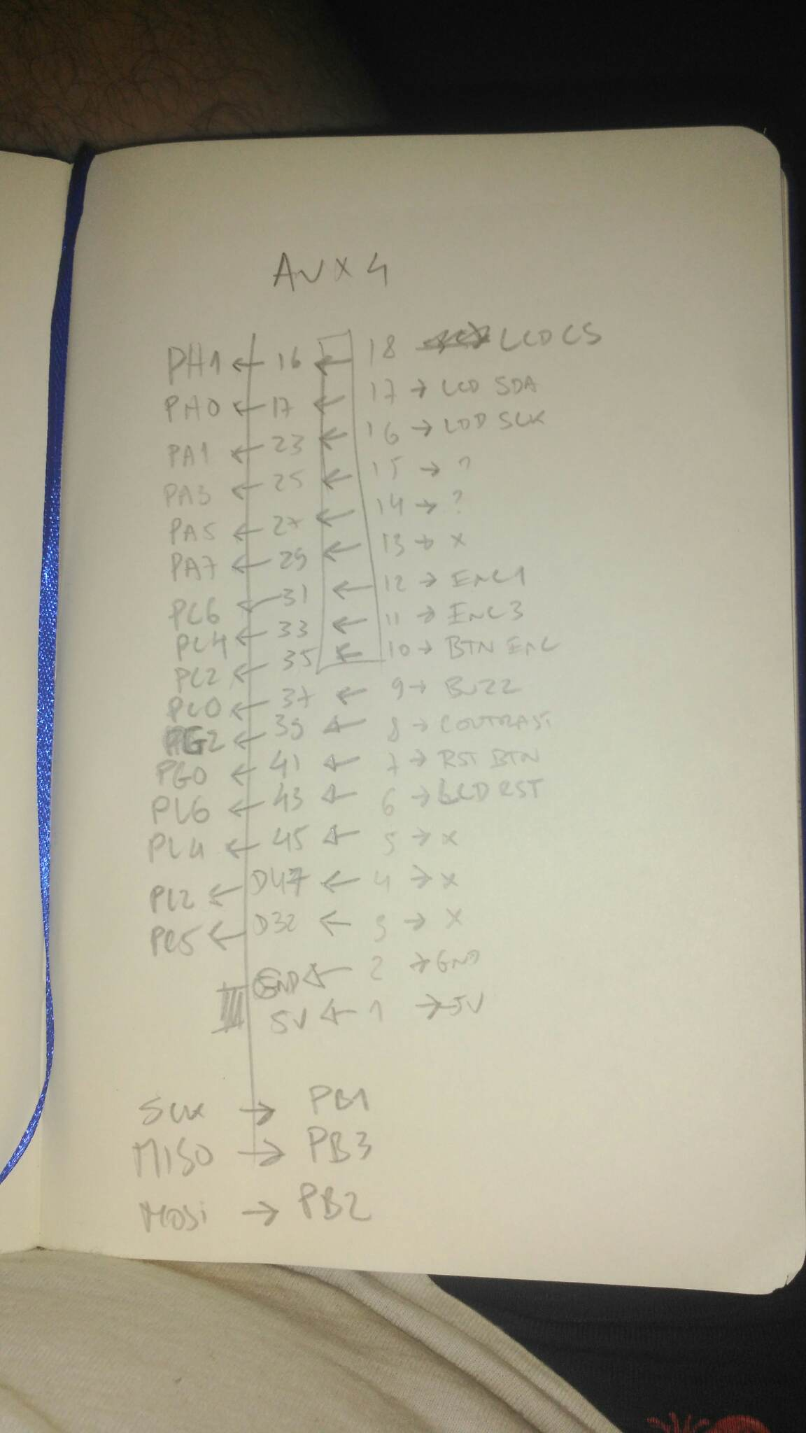
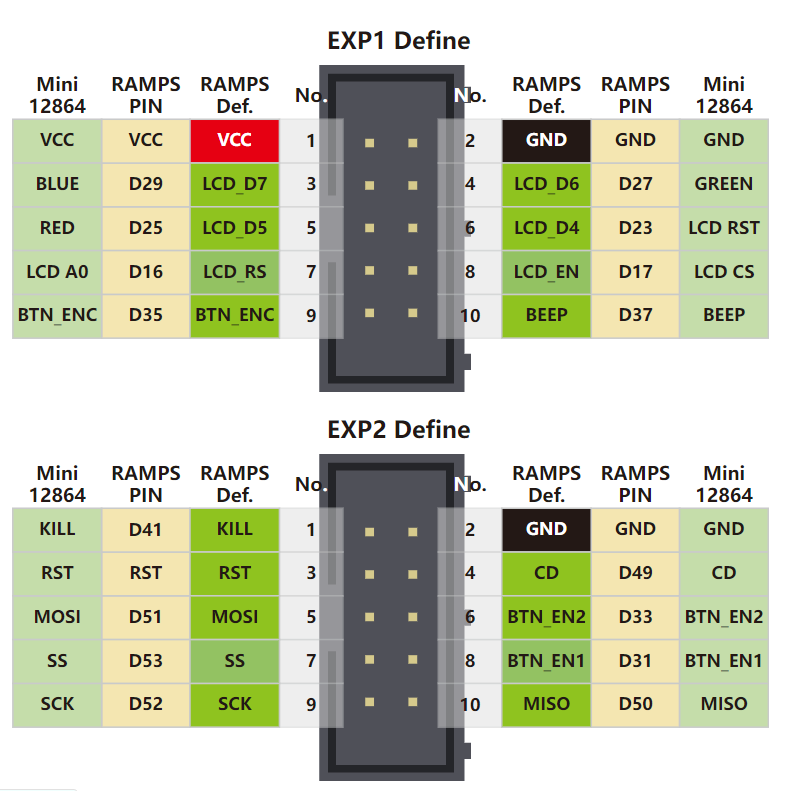
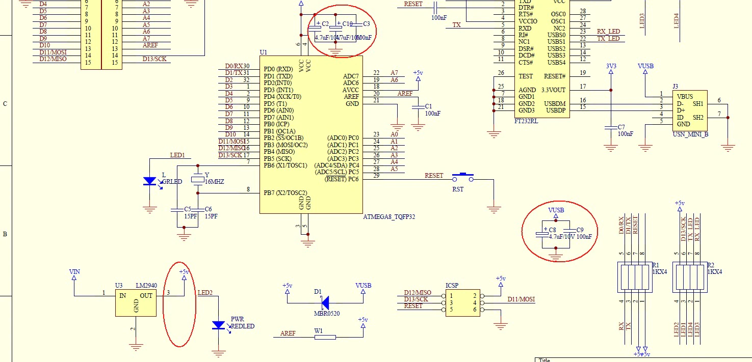
- BQ LCD Schematic
- BQ LCD connector Schematic
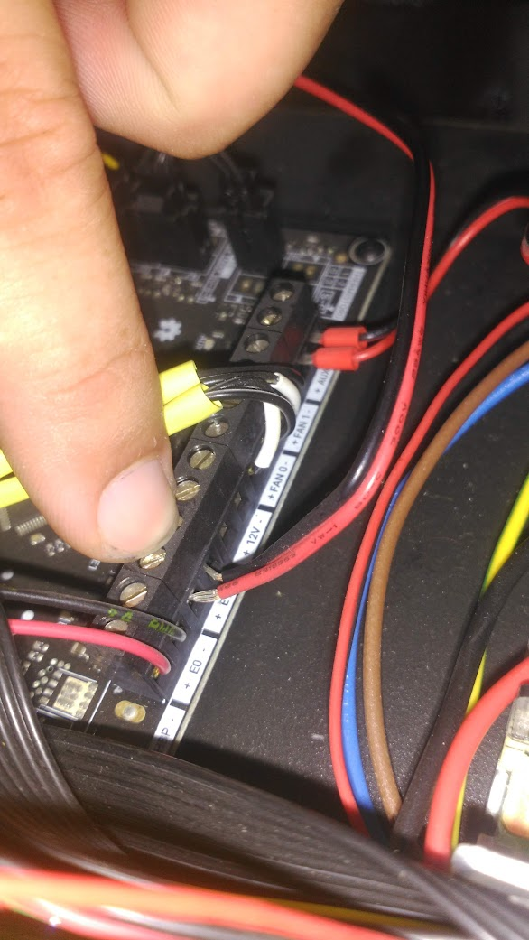
- BQ Witbox 2 electronic Schematic
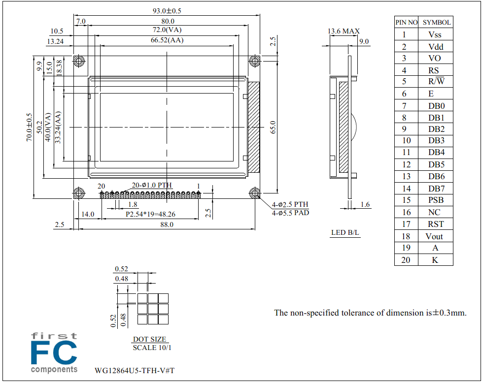
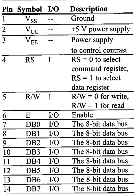
- LCD Datasheet that the machine is using
| Brand | Winstar |
|---|---|
| Size | 2.9" |
| Resolution | 128x64 |
| Active Area (mm) | 66.52x33.24 |
| Dot Size | 0.48x0.48 |
| B/L color, LCD type | B/L white, FSTN white pos |
| Power supply | 5V |
| Display Interface | 6800 |
| Display IC Controller | ST7920 |
| Constructive Structure | COB |
| View Angle | 6H |
| Frame | Yes |
| Touch Panel | No touch |
| O. Temperature (°C) | -20~70 |
| Display Connection | Soldering PAD |
| Pin Nr. | 20 |
| Pin Pitch | 2.54mm |
| Preferred - Not Preferred | Not Preferred |
----
MARLIN CONFIG

#ifdef BQ_LCD_SMART_CONTROLLER
 # Reset Button
 #define KILL_PIN            41 = PG0 = kill_pin
 # LCD
 #define LCD_PIN_BL          39 = PG2
 #define LCD_PINS_RS         16 = PH1 = cs_pin
 #define LCD_PINS_ENABLE     17 = PH0 = sid_pin
 #define LCD_PINS_D4         23 = PA1 = sclk_pin
 # Button & Encoder
 #define BTN_EN1             31 = PC6 = encoder_pins [1]
 #define BTN_EN2             33 = PC4 = encoder_pins [2]
 #define BTN_ENC             35 = PC2 = click_pin
 # Buzzer
 #define BEEPER              37 = PC0
 # SD Card Reader
 #define SDSS                53 = PB0
 #define SDCARDDETECT        49 = PL0
So it turns out it was the contrast. everything was displaying with the pin mapping i had found but was not showing since the contrast was se to 0 basically
This also added a neat slider to the fluidd screen that allows to set contrast 🙂
Thanks Master @JamesH[E3v2] at klipper config discord channel for all the help

Final code looks like this
lcd_type: st7920
cs_pin: PH1
sclk_pin: PA1
sid_pin: PH0
encoder_pins: ^PC4,^PC6
click_pin: ^!PC2
kill_pin: ^!PG0

[output_pin LCD_contrast]
pin: PG2
pwm: true
value: 0.95
cycle_time: 0.001

[output_pin beeper]
pin: PC0
i211007 TODO:
- Install klipper/fluidd
- Write and test printer configs
- XYZ correct homing and printer boundaries
- Run recommended configuration checks
- Run recommended bed levelling guide
- Confirm: Fan case is implemented?
- Confirm: E0 part fan is implemented?
- Confirm: E0 heatbreaker fan is implemented?
-
Implement and calibrate: bed screw level assisted tilt level - Implement and calibrate: probe-nozzle offset
- Do a print-test before next phase
- Implement and calibrate: resonance compensation
- Implement and calibrate: pressure advance
- Do a print-test and compare
- Cleanup printer config files and separate macros from config with include function
- Write up instalation and caveats documentation
- Convert gist to a repo and share machine conversion
- Create a generic printer.cfg and submit a pr following klipper contribute guidelines
- Add boot logo to the LCD for kicks as described in reddit
- Add stormpi UPS to safely power down the machine when mains is cut
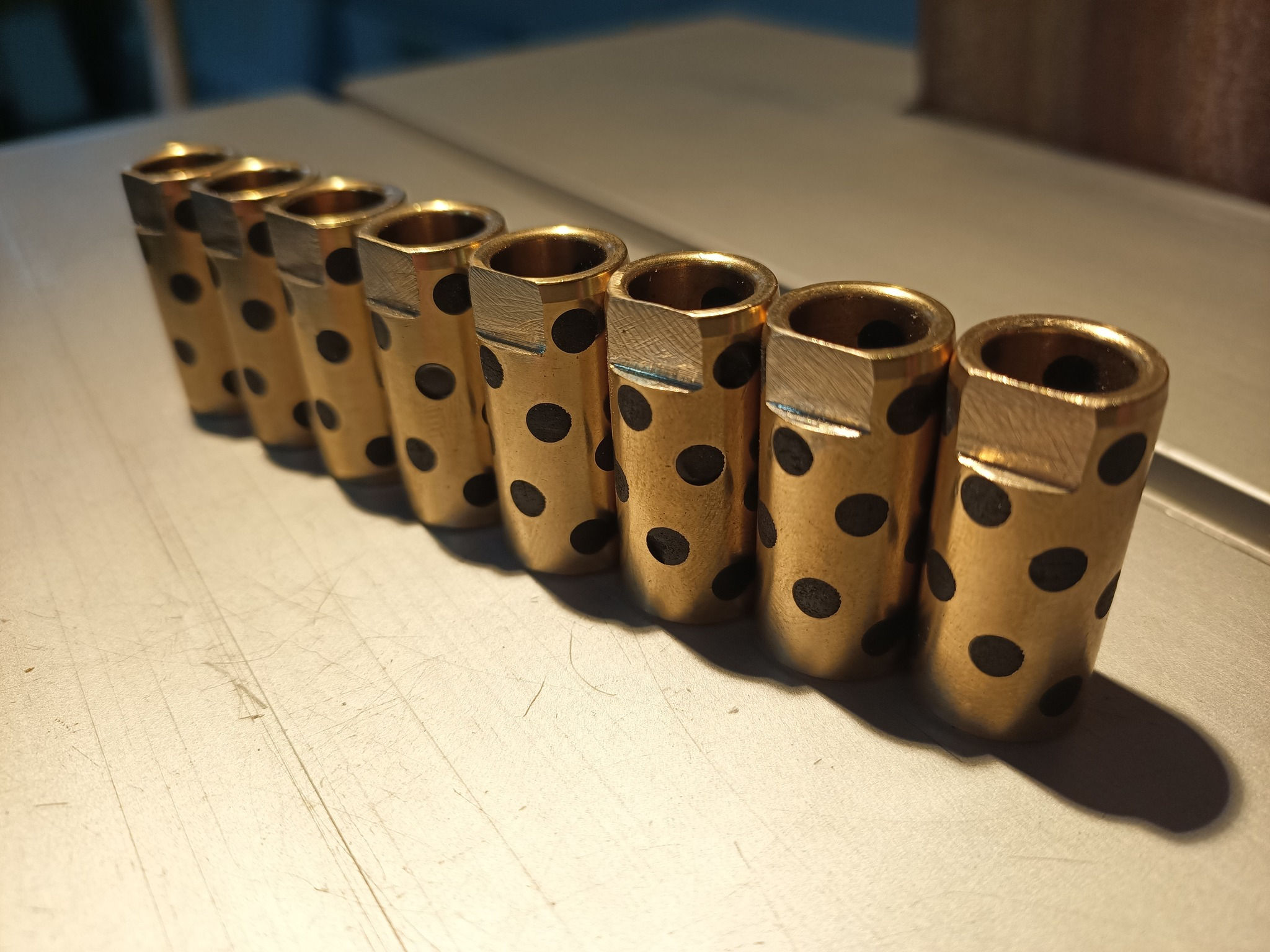
- Reinforce XY axis with beefier axels, graphite brass bushings and support needle bearings
- Replace XY belts with new ones and replace pulleys with brass ones
- Diy and implement a filament runout sensor & respective macro
- Find why printer native lcd is not working
- Wire up the new heated bed to the printer and tie it to klipper logic
- Install ideamaker
- Add printer and printer profiles as per configuring a slicer with klipper
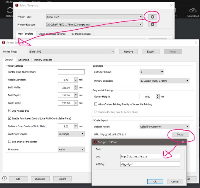
- Register printer to file network file send like this example api key is watever one wants
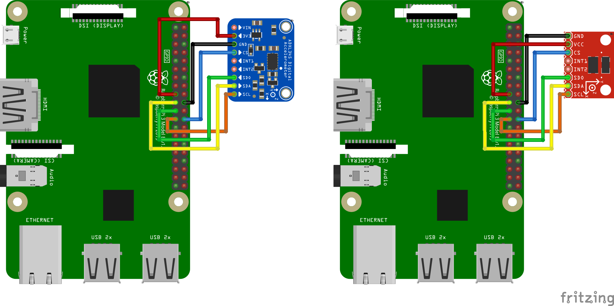
Mesuring Resonance with ADXL345
https://www.klipper3d.org/Measuring_Resonances.html
SSH
# Install numpy (20min+)
~/klippy-env/bin/pip install -v numpy

# Install additional dependencies
sudo apt update
sudo apt install python-numpy python-matplotlib
Enable RPI as additional MCU (if not already enabled)
# Install the rc script
cd ~/klipper/
sudo cp "./scripts/klipper-mcu-start.sh" /etc/init.d/klipper_mcu
sudo update-rc.d klipper_mcu defaults

# Enable SPI in piconfig
sudo raspi-config
    Interfacing options -> SPI -> YES -> OK -> Finish

# Build secondary microcontroller code
cd ~/klipper/
make menuconfig
    Microcontroller Architecture -> Linux process -> exit -> save

# Install secondary mcu code
sudo service klipper stop
make flash
sudo service klipper start
Changes to printer config
[mcu rpi]
serial: /tmp/klipper_host_mcu

[adxl345]
cs_pin: rpi:None

[resonance_tester]
accel_chip: adxl345
probe_points:
    148,105,20  # Probe point is the nozzle position when testing; Ideally center bed slightly above it
If all goes well one can test and use the sensor via the fluidd console with these commands
# To query and confirm installation on fluidd command terminal
ACCELEROMETER_QUERY

# To check the sensor noise; OK = between 1-100 ; Above 1K = sensor problems
MEASURE_AXES_NOISE

#To do the test
TEST_RESONANCES AXIS=X
TEST_RESONANCES AXIS=Y
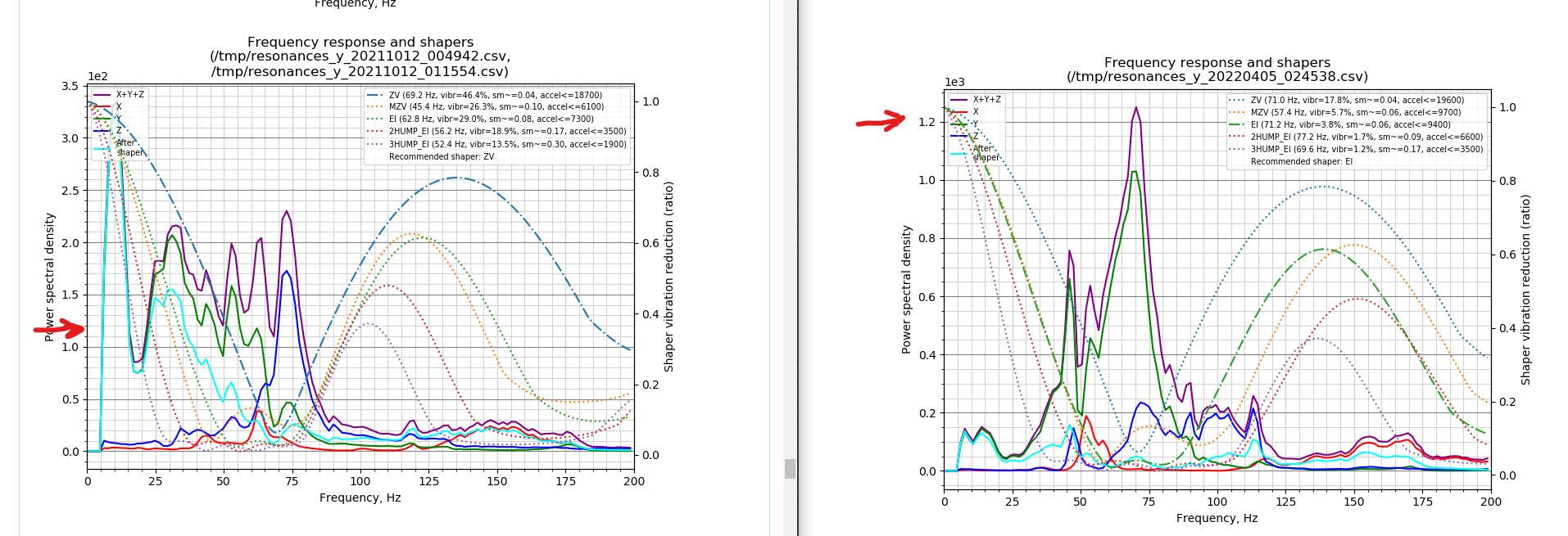
TEST_RESONANCES will generate 2 CSV files (/tmp/resonances_x_.csv and /tmp/resonances_y_.csv). These files can be processed with the stand-alone script on a Raspberry Pi. To do that, run running the following commands:
~/klipper/scripts/calibrate_shaper.py /tmp/resonances_x_*.csv -o ~/klipper_config/shaper_calibrate_x.png
~/klipper/scripts/calibrate_shaper.py /tmp/resonances_y_*.csv -o ~/klipper_config/shaper_calibrate_y.png
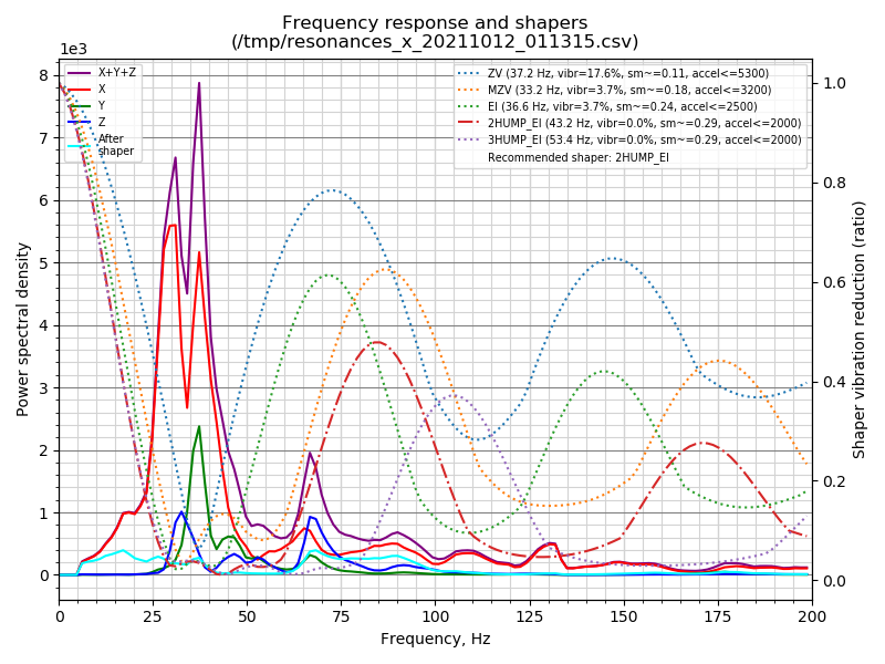
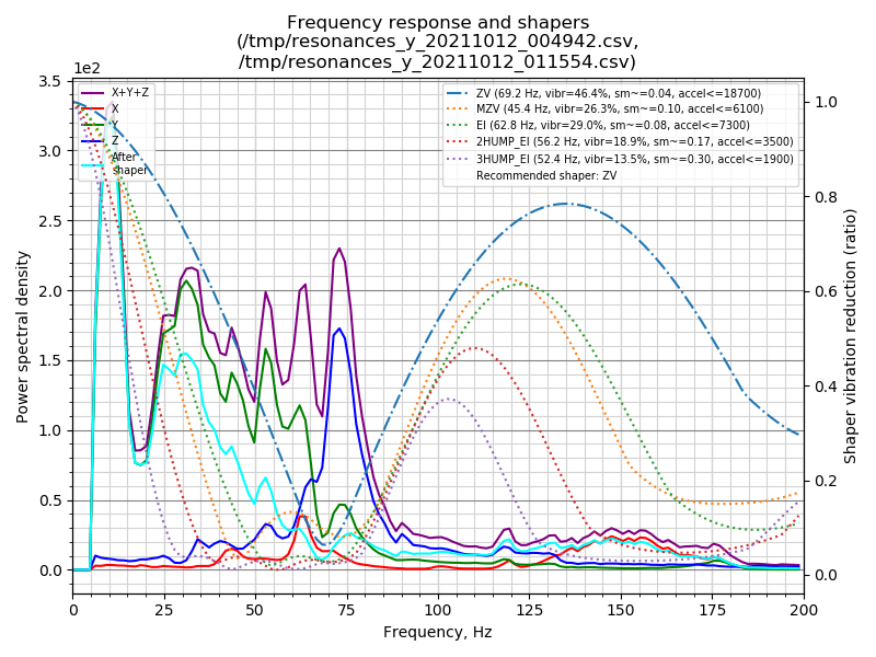
This script will generate the charts /tmp/shaper_calibrate_x.png and /tmp/shaper_calibrate_y.png with frequency responses. You will also get the suggested frequencies for each input shaper, as well as which input shaper is recommended for your setup. For example:
Pi track install changes
- fswebcam (trying to capture from elp camera)
- fbi (display images on terminal)
Adding webcam to klipper (mansail) but works also for fluidd via MJPG-STREAMER
https://3dp.tumbleweedlabs.com/firmware/klipper-firmware/adding-webcam-support-to-mainsail
start test stream:
/usr/local/bin/mjpg_streamer -i "input_uvc.so -f 5 -r 1280x720" -o "output_http.so -w /usr/local/share/mjpg-streamer/www"

safe stop stream:
ctrl^c
#TOFIX: first homing issues
https://youtu.be/409MwuZNUYA
https://github.com/Klipper3d/klipper/blob/master/klippy/extras/safe_z_home.py
Macro Creation Tutorial
https://klipper.discourse.group/t/macro-creation-tutorial/30/2
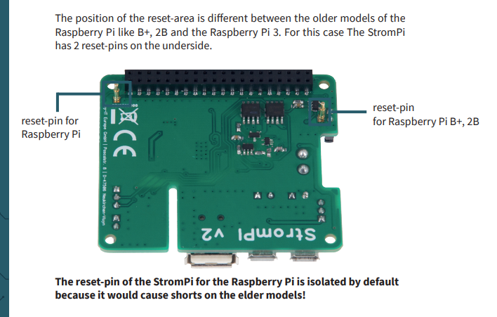
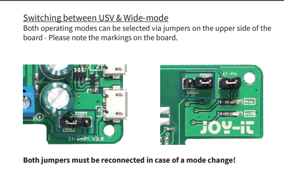
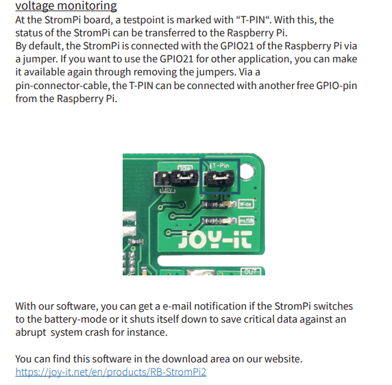
Adding Strompi2 UPS
https://joy-it.net/files/files/Produkte/RB-StromPI2/RB-StromPi2-Manual.pdf
Adding the UPS the raspi will allow normal power off via mains power button with safe shutdown of the pi and auto reboot when power is restored.
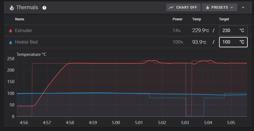
Adding the hotbead to the Witbox2

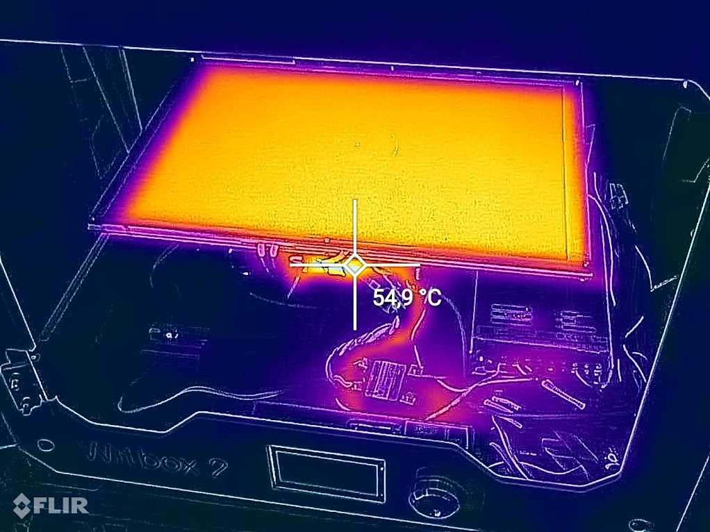

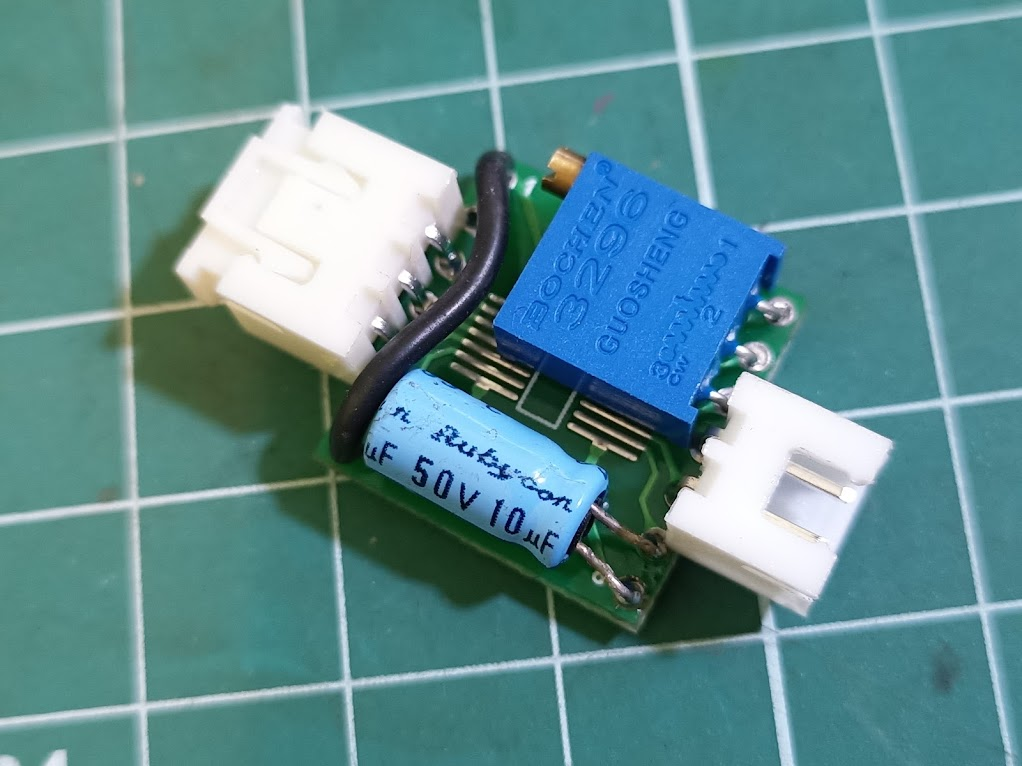
Standalone code to test and validate the circuits before adding it to klipper controll
int ThermistorPin = A6;
int Vo;
float R1 = 10000;
float logR2, R2, T, Tc, Tf;
float c1 = 1.009249522e-03, c2 = 2.378405444e-04, c3 = 2.019202697e-07;

int readAverage(byte pin = ThermistorPin, byte num_readings = 10)
{
  int result = 0;
  for (byte i = 0; i < num_readings; i++)
  {
    result += analogRead(pin);
    delay(50);
  }
  return result / num_readings;
}

int led_pin=13;

void setup() {
pinMode(2, OUTPUT);
pinMode(led_pin, OUTPUT);

Serial.begin(9600);
}

void loop() {

  Vo = readAverage();
  R2 = R1 * (1023.0 / (float)Vo - 1.0);
  logR2 = log(R2);
  T = (1.0 / (c1 + c2*logR2 + c3*logR2*logR2*logR2));
  Tc = T - 273.15;
  Tf = (Tc * 9.0)/ 5.0 + 32.0;

  //Serial.print("Temperature: ");
  //Serial.print(Tf);
  //Serial.print(" F; ");
  Serial.print(Tc);
  Serial.println(" C");

  delay(100);

  if (Tc < -20){
    digitalWrite(2, LOW);
    digitalWrite(led_pin, HIGH);
    Serial.print("Temperature Error!");
  }
  if (Tc > 0){
    digitalWrite(led_pin, LOW);
  }

  if (Tc < 50 && Tc > -20){
    digitalWrite(2, HIGH);
  }
  if (Tc > 50){
    digitalWrite(2, LOW);
  }
  }
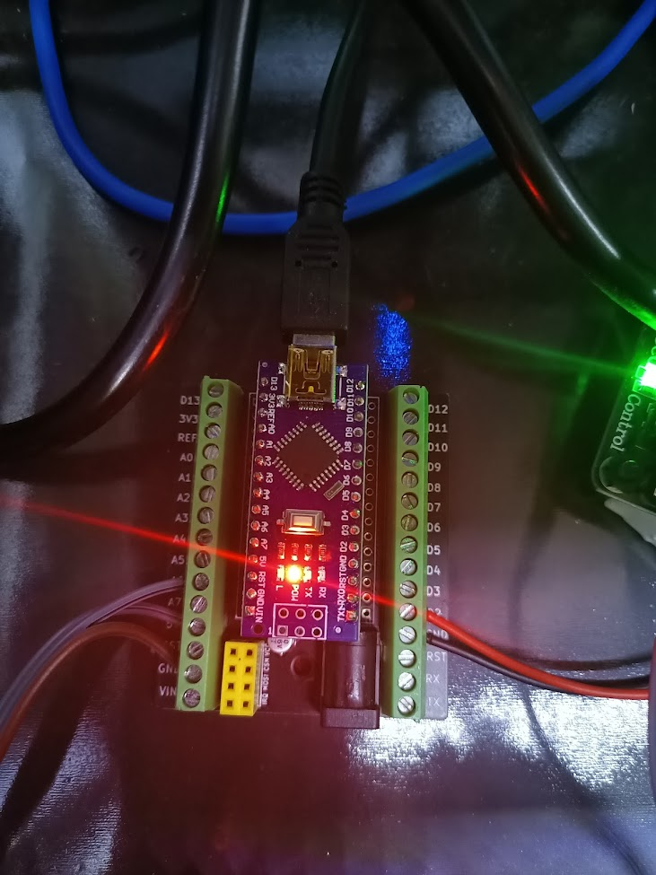
After testing adding the new mcu to klipper
https://www.klipper3d.org/Installation.html#building-and-flashing-the-micro-controller
Before brass graphite brushings update and after
(https://www.facebook.com/permalink.php?story_fbid=10160069552753680&id=651553679)

Before bed mesh probing, make sure you calibrate your probe distance to your bed.
PROBE_ACCURACY
PROBE_CALIBRATE
- TESTZ Z=-1 (value to move down to go to the paper)
- TESTZ Z=+1
Replacing the Extruder Motor
So i've decided to try replacing the extruder motor with a lighter bondtech pancake stepper, but this motor asks for 0.7A per coil instead of 1.7A, so i just used altium online viewer to check where the VREF was going and turns out it is using a digital resistor.
With the part reference i decided to check klipper repo and found it already has a implementation for this ad5206 digital resistor
Support for run-time configuration of TMC2130, TMC2208/TMC2224, TMC2209, TMC2660, and TMC5160 stepper motor drivers. There is also support for current control of traditional stepper drivers via AD5206, MCP4451, MCP4728, MCP4018, and PWM pins. reference link
Run-time stepper motor current configuration ad5206

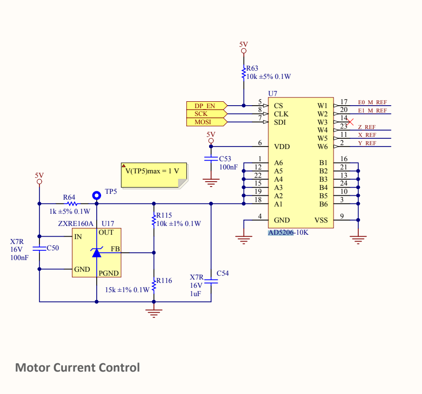

[ad5206 stepper_digipot]
enable_pin: PA0
scale: 2.0
# Channel 1 is E0, 2 is E1, 3 is unused, 4 is Z, 5 is X, 6 is Y - Value is Amps
channel_1: 0.7
channel_2: 0.7
channel_4: 1.7
channel_5: 1.7
channel_6: 1.7
hello @X3msnake! did your upgrade succeed? I just got old witbox 2, and I was wondering if it's worth investing some time.
yes it works fine
Hi @X3msnake, congratulations by your awesome job. I've made similar upgrade on my old witbox 2 too, but I've modified x axis to install a mk3 carriage, and installed a mk3 heatbed too, an eninsy rambo, PINDA, E3D V6, bondtech gears etc. And I can use same config slicer of mk3 or mk4. All works great. So I want to give you thanks by your info about ST7920 LCD, now mine works great. Thank you!!
@fanchunfa Awsome Master, glad it helped, thank you for taking time to confirm it worked with Your build.
Hello, the work you have done is incredible!. I'm not sure how to do this update to my Witbox2, could I install the Klipper firmware without modifying the heated bed?
@SeeN1975
Yes, the config is modular so you can basically copy all config files to your klipper instalation, then modify printer.cfg and comment out the bed heater
# Heatbed external board atmega 328p
# [include witbox2_heatbed_mcu.cfg]
@SeeN1975 Yes, the config is modular so you can basically copy all config files to your klipper instalation, then modify printer.cfg and comment out the bed heater
# Heatbed external board atmega 328p
# [include witbox2_heatbed_mcu.cfg]
Thanks for the clarification! To burn the firmware, do you do it from kiauh directly via USB?

Could you tell me if these parameters are correct?
Download all .cfg files and rename and upload it via browser in fluiddpi.local under configuration files menu
https://www.klipper3d.org/Installation.html#building-and-flashing-the-micro-controller
AFTER ADDING CFG files
SSH into the fluiddpi image with putty host: fluiddpi.local; port:22 user: pi; pass: raspberry
cd klipper sudo service klipper stop make menuconfig esc / save make wait for build complete ls /dev/serial/by-id/* copy listed serial port make flash FLASH_DEVICE=/dev/serial/by-id/usb-FTDI_FT232R_USB_UART_A503SQIW-if00-port0 wait for flash sucessfull complete
AFTER SUCESSFULL FLASH
make menuconfig change microcontroller to linux processor / enter / esc / esc / save make flash wait for build complete sudo service klipper start
I'll explain all the steps.
Firmware Configuration
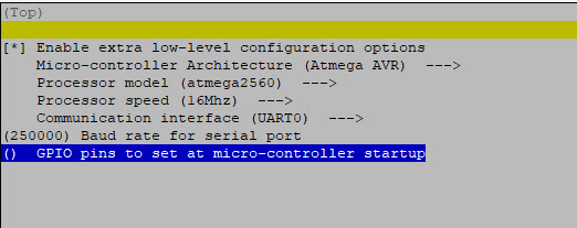
Burn firmware

Now the printer screen has gone blank.
Klipper shows this error.

Baud rate most likely

https://www.reddit.com/r/klippers/comments/skgf5f/mcumcu_unable_to_connect/?rdt=47922
PROBABLE ISSUES
If you get ‘i2c_config’ has incomplete type you propably ran menuconfig twice without a make after
solution is to issue the following commands:
make clean
git pull
make menuconfig (again)
make
source: Klipper3d/klipper#4409
flash fails with ioctl("TIOCMGET")
your flash command is missing "/dev/serial/by-id/" You need to provide the full path to the device, not just its ID
Klipper3d/klipper#2266